Realizzazione di un termostato con AD595 - ViaLeopardiCinque
Menu principale:
Realizzazione di un termostato con AD595
Progetti
Realizzazione di un termostato con AD595
© 2014 Giuseppe Rapporti
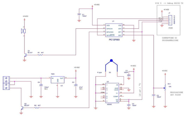
Una termocoppia di tipo K è collegata all'ingresso dell'AD595 che rende disponibile in uscita il valore di 10mV per grado. L'uscita VO/FB dell'AD595 (10mV/°C) è collegata all'ingresso analogico AN1 del microcontrollore U1, mentre il set-point viene impostato mediante la regolazione del trimmer multigiri RV1 collegato all'ingresso analogico AN2 di U1. All'avvio del termostato, verrà eccitato il relay collegato a Q2 attivando così la resistenza di riscaldamento. Successivamente Il microcontrollore eseguirà un campionamento al secondo sui due ingressi analogici, confronterà il valore della temperatura misurata con il valore del set point impostato, e se la temperatura è maggiore del set point allora verrà portata a zero l'uscita GP5 di U1 diseccitando quindi il relay collegato al transistor Q2, il relay verrà nuovamente eccitato solo al raggiungimento del valore impostato sul set point meno il valore di isteresi programmato. Se la temperatura dovesse superare il valore di soglia di allarme programmato, allora verrà attivato il segnalatore acustico collegato a Q1.

CODICE SORGENTE
//////////////////////////////////////////////////////////////////////////////////////////
/*
Name : PIC_12F683_AD595_TERMOSTATO_1_0.c
Author : Giuseppe Rapporti
Notice : Copyright (c) 2014
: All Rights Reserved
Version : 1.0
Notes : PIC 12F683
Versione 1.0
*/
//////////////////////////////////////////////////////////////////////////////////////////
#include <PIC_12F683_AD595_TERMOSTATO_1_0.h>
#ZERO_RAM
unsigned int16 read_AD595(void);
unsigned int16 read_set_point(void);
void main()
setup_wdt(WDT_OFF); // SWDTEN = 0
setup_oscillator(OSC_8MHZ);
setup_adc_ports(AN2_ANALOG | VSS_VDD); // Vref = Vdd
setup_adc(ADC_CLOCK_DIV_2); // Clock ADC converter
set_adc_channel(2); // GP2 = Ingresso analogico
setup_comparator(NC_NC); // Non viene uato il comparatore
setup_vref(FALSE); // Non viene usata la Vref del comparatore
setup_timer_0(RTCC_INTERNAL);
setup_timer_1(T1_INTERNAL|T1_DIV_BY_1); // 1 = 0,5uS - overflow (65535) ogni 32,8mS
set_timer1(OVERFLOW_30); // overflow ogni 30uS
enable_interrupts(global);
disable_interrupts(INT_TIMER1);
fprintf(COM1,"** AD595 TERMOSTATO V1.0 **");
output_high(RELAY); // relay ON
output_low(DEBUG_TX); // debug TX init...
output_low(BUZZER); // buzzer OFF
delay_ms(STARTUP_DELAY);
setup_wdt(WDT_DIV_65536); // Start WDT=2,4 Sec
while(1)
restart_wdt();
tcelsius = read_AD595();
if(tcelsius > TEMP_ALARM ) output_high(BUZZER); else output_low(BUZZER);
set_point = read_set_point();
fprintf(COM1,"Temp: %lu Set Point: %lu",tcelsius,set_point);
if ( tcelsius >= set_point ) output_low(RELAY);
if ( tcelsius < (set_point-ISTERESI) ) output_high(RELAY);
delay_ms(1000);
restart_wdt();
///////////////////////////////////////////////////////////////////////////////
/*
FUNCTION: read_AD595(void)
DESCRIPTION: Legge l'uscita dell'AD595 10mV/°C
PARAMETERS:
RETURNS: temperatura misurata
*/
////////////////////////////////////////////////////////////////////////////////
unsigned int16 read_AD595(void)
long d;
unsigned int32 akku;
long mvolt;
restart_wdt();
setup_adc_ports(AN1_ANALOG | VSS_VDD); // Vref = Vdd
set_adc_channel(1); // GP1 = Ingresso analogico
delay_ms(100);
d=read_adc();
akku = (unsigned int32) d * QUANTO;
mvolt = (unsigned int16) (akku / 100);
return (mvolt);
///////////////////////////////////////////////////////////////////////////////
/*
FUNCTION: read_set_point(void)
DESCRIPTION: Legge il potenziometro di regolazione del set point
PARAMETERS:
RETURNS: set point impostato
*/
////////////////////////////////////////////////////////////////////////////////
unsigned int16 read_set_point(void)
long d;
unsigned int32 akku;
long mvolt;
restart_wdt();
setup_adc_ports(AN2_ANALOG | VSS_VDD); // Vref = Vdd
set_adc_channel(2); // GP1 = Ingresso analogico
delay_ms(100);
d=read_adc();
akku = (unsigned int32) d * QUANTO;
mvolt = (unsigned int16) (akku / 100);
return (mvolt);
//////////////////////////////////////////////////////////////////////////////////////////
/*
Name : PIC_12F683_AD595_TERMOSTATO_1_0.h
Author : Giuseppe Rapporti
Notice : Copyright (c) 2014
: All Rights Reserved
Version : 1.0
Notes : PIC 12F683
*/
//////////////////////////////////////////////////////////////////////////////////////////
#include <12F683.h>
#device adc=10
#fuses NOWDT //Wdt disabled and can be enabled by SWDTEN bit of the WDTCON register
#fuses INTRC_IO // Internal RC Osc, no CLKOUT
#fuses NOCPD // No EE protection
#fuses NOPROTECT // Code not protected from reading
#fuses NOMCLR // Master Clear pin disabled
#fuses NOBROWNOUT // Brown-out Reset disabled in hardware and software
#fuses NOPUT // no Power Up Timer
#fuses NOIESO // NO Internal External Switch Over mode enabled
#fuses NOFCMEN // Fail-safe clock monitor disabled
#use delay(clock=8000000)
#define DEBUG_TX PIN_A0 //
#define AD595_VO PIN_A1 //
#define POT PIN_A2 //
#define GP3 PIN_A3 //
#define RELAY PIN_A4
#define BUZZER PIN_A5
#use rs232(baud=9600,parity=N,xmit=DEBUG_TX,rcv=PIN_A3,bits=8, stream=COM1, FORCE_SW, invert)
#bit ULPWUE = 0x8E.5 // ultra low power wake up enable bit
#bit SBOREN = 0x8E.4 // software BOR enable bit 1=BOR enabled
#bit POR = 0x8E.1 // power on reset status bit
#bit BOR = 0x8E.0 // brown-out reset status bit
#bit IOC3 = 0x96.3 // Interrupt on change GPIO3
#bit RP0 = 0x03.5 // bank select
#bit PWM1 = 0x05.2 // RFID_COIL-PIN_A2
#bit T_POINT = 0x05.4 // GP4-PIN_A4
#bit TMR2ON = 0x12.2
#bit TMR2IF = 0x0C.1
#bit CMIF = 0x0C.3 // Comparator interrupt flag bit
#bit COUT = 0x19.6 // Comparator output
#bit GPIE = 0x0B.3 // GPIO Change Interrupt Enable bit 1=enabled
#bit GPIF = 0x0B.0 // GPIF GPIO Change Interrupt Flag bit
// 1 = When at least one of the GPIO <5:0> pins changed state (must be cleared in software)
#byte CCP1CON = 0x15 //
#byte TMR2 = 0x11 // Timer 2 mudule register
#byte PR2 = 0x12 // 0x92 BANK 1 Timer 2 Module Period Register
#byte CCPR1L = 0x13 // capture compare PWM register 1 Low byte
#byte INTCON = 0x0B // Interrupt control register
#byte STATUS = 0x03
#byte TRISIO = 0x05 // 0x85 BANK 1
#byte PIE1 = 0x0C // 0x8C BANK 1
#byte PIR1 = 0x0C // Peripheral interrupt request register 1
#byte T2CON = 0x12
#byte CMCON0 = 0x19 // Comparator configuration register
#byte CMCON1 = 0x1A // Comparator configuration register
#define STARTUP_DELAY 1000 // Delay iniziale 1500
long set_point;
long tcelsius;
#define QUANTO 488 // = 5 / 1024 = 0,0048828125 (* 100K)
#define ISTERESI 200 // 20°C isteresi (1°C = 10)
#define TEMP_ALARM 2500 // 250°C (1°C = 10)